Description
iPod Audio Capacitor ByPass Kit
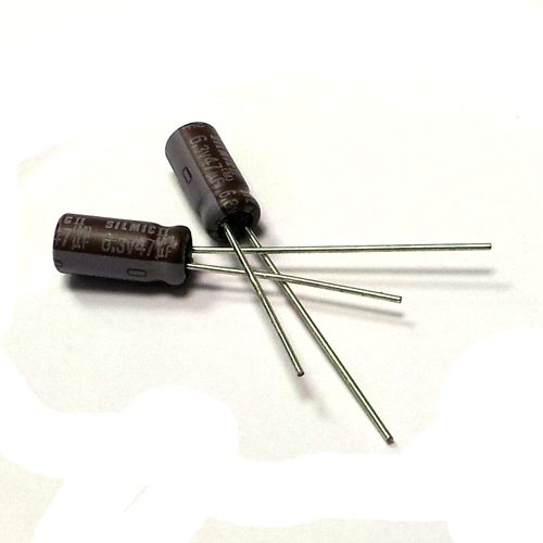
ELNA Silmic II Capacitors
Sometimes known as the DiyMod – use the extra space created by upgrading to an iFlash adapter to install some high quality bypass audio capacitors in place of the factory surface mount capacitors.
This kit comes with everything you need to perform the mod but will require the following tools: soldering iron, mini philips screwdriver, small drill and plenty of skills!!
Please note to do this mod requires a soldering iron and fine soldering skills – please make sure you are able to do the mod or have someone who can do it for you, as returns are not accepted for this product, only buy if you know what you are doing!!
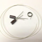
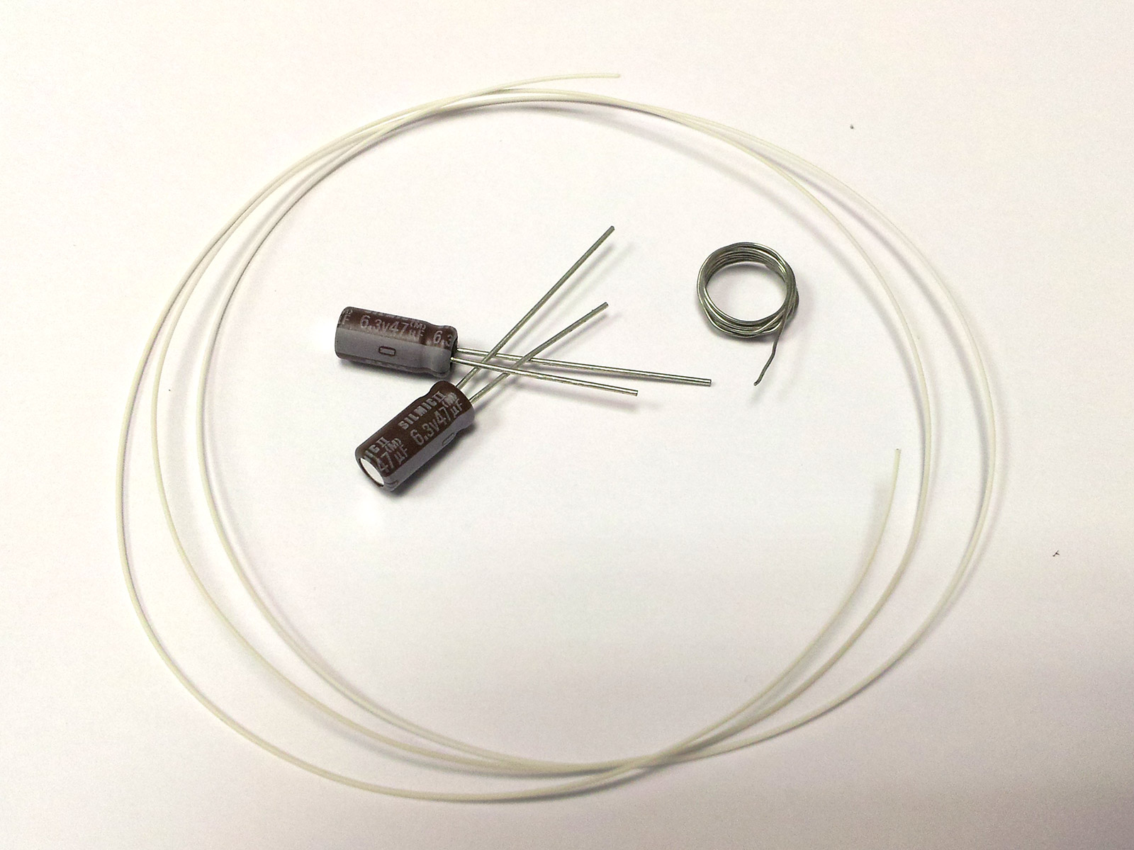
DiyMod Kit
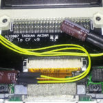
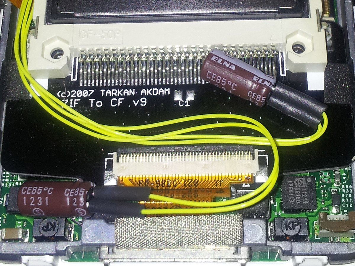
DiyMod Installed
Kit Includes
- ELNA Silmic-II 6.3v 33uf (x 2) Audio Capacitors
- High silver content (3%) solder wire (30cm/12″)
- Silver-plated Oxygen Free Copper solid core 30awg (0.5mm) wire (45cm/17″)
- heatshrink tubing (5cm/2″)
Compatibility
- iPod 5g Video 30Gb, 60Gb
- iPod 5.5g Video 30Gb, 80Gb
- Only suitable for Wolfson based iPods
- Will work with all iFlash adapters (iFlash-CF, iFlash-Quad, iFlash-Solo, and iFlash-Dual)
NOTE: Due to stock issues we will be changing the capacitors to 33uf ELNA Silmic-II capacitors once our stock of 47uf are used up. This has no effect on the audio quality of these excellent capacitors in the iPod.
Installation
This Audio-Kit is for people who already know what they are doing, and hence we do not have a full install guide.
If you need a full install guide then this audio-kit is not for you! You may be able to find more suitable guides online if you search for ‘DiyMOD’.
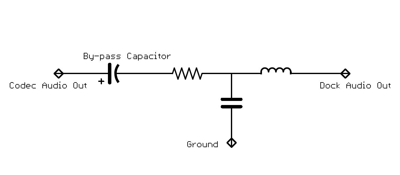
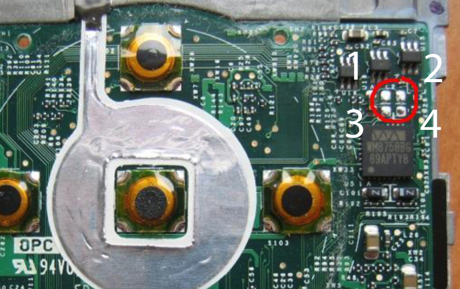
iPod Dock Audio output circuit looks something like this. The audio output from the Codec goes through a SMT aluminium bypass capacitor to remove the bias voltage that sits on this pin. Then through a small current limiting resistor and finally a RFI low-pass type filter arrangement (capacitor/inductor) to stop RF noise entering/leaving the iPod.

iPod audio output circuit
The bypass capacitor has to be removed and then you have a choice to place the new capacitor where the original capacitor goes in, or as some people prefer putting the capacitor between the codec output and dock audio out pin.
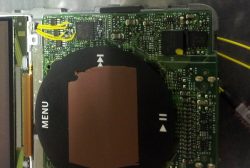
When we do this mod our method is to insert the new capacitors between the pads of the original SMT capacitors.
Using the pad numbers in the image shown below for an 5g iPod, we attach the first capacitor + to Pad 3 and then capacitor – to Pad 1, then do the same with the second capacitor (Pad 2 and Pad 4).

Pad 1 is (-) Negative Pin of Audio 1
Pad 3 is (+) Positive Pin of Audio 1
Pad 2 is (-) Negative Pin of Audio 2
Pad 4 is (+) Positive Pin of Audio 2
Wiring soldered to pads
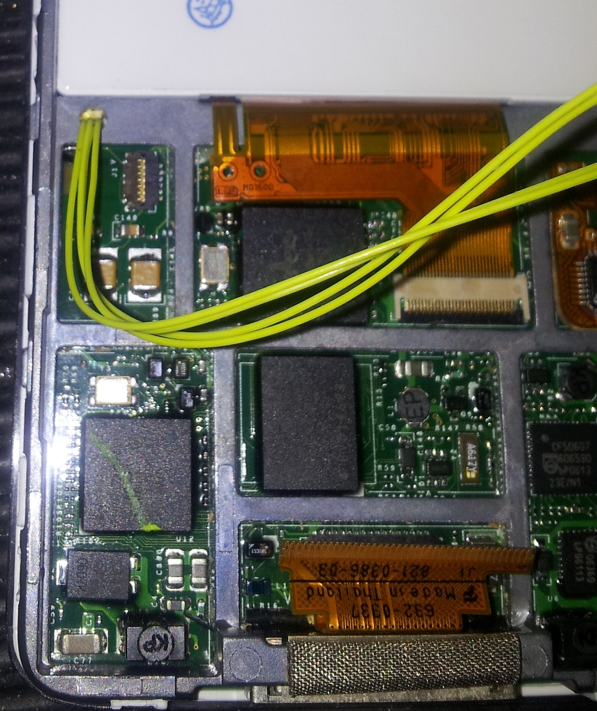
You will also have to drill the necessary holes to pass the wires through the iPod chassis to the other side where you have space to house the capacitors.

Wires passed through iPod Chassis
Good luck and good soldering.